The Predict Mud Weight view
The Predict Mud Weight view click to enlarge
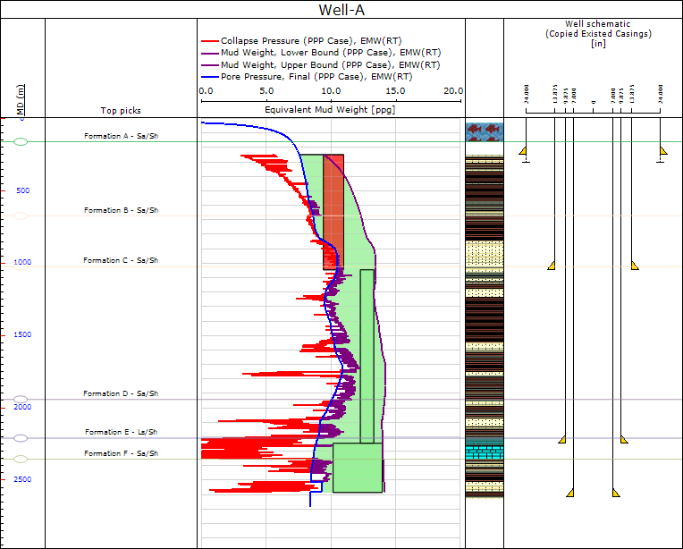
The Predict Mud Weight view enables you to analyze the mud weight window and different casing designs. The plot in the center of the window showing mud weights displays the pore pressure, collapse pressure, and the fracture pressure that define the mud window (green shaded area) as a function of depth. The application calculates these three dimensional borehole stresses from formulas by Hiramatsu and Oka (1962). In this view, you can define custom mud weights by opening the Define MW Program form (Wellbore Stability > Predict Mud Weight > Tools) and clicking a trend line in the view.
Mud window
The mud window is the difference between the lowest and highest acceptable mud weights for a given set of drilling conditions.
Lower bound
You can define the mud weight lower bound as:
- pore pressure (common industry standard)
- borehole collapse pressure (guarantees that the width of borehole breakouts does not exceed the given limit)
- maximum of these two (the default selection)
Upper bound
You can define the upper bound of the mud window as :
- least principal stress (the default selection)
- fracture gradient
You can change either bound on the mud window in Step 1.
The following are the available options for the lower and upper bound constraints.
Lower bound constraint
Collapse Pressure Sets the calculated collapse pressure as the lower bound for the algorithm.
Pore Pressure Sets the calculated pore pressure as the lower bound for the algorithm.
Maximum of Pore & Collapse Pressure Selects the maximum of the two bounds to be used as the lower bound in the algorithm
Upper bound constraint
Minimum Stress The least principal stress of the three main principal stresses.
Fracture initiation pressure (Pinit) Fracture initiation pressure is the mud pressure at which a tensile fracture starts to form on the wellbore wall for a given tensile strength. The tensile strength is often very close to zero since preexisting flaws or irregularities are usually present on the wall. Both the fracture initiation pressure and orientation of the tensile fractures are sensitive to the in-situ stress and to borehole orientation; fractures are not axial if the borehole axis is not in a principal stress plane. From the viewpoint of wellbore stability however, the fracture initiation pressure is usually not dangerous because fractures are still small and do not result in lost circulation.
Fracture link-up pressure (Plink) Fracture link-up pressure is the mud pressure at which isolated, non-axial fractures begin to link up. At this stage, the fracture openings are much larger than at fracture initiation, which may lead to some lost fluid; this fluid may be recovered if the wellbore pressure drops, for example, while making connections. Such cyclic gains and losses may be the explanation for ballooning that is often reported in deepwater wells. The calculations of the link-up pressure are based on a theory presented by Ito et al. (1999). The link-up pressure is dependent on wellbore orientation, which means that in certain cases, lost circulation problems may be avoided by changing the directional orientation of the well.
Fracture grow pressure (Pgrow) Fracture grow pressure (also called fracture propagation pressure) is the mud pressure necessary to drive fracture propagation away from the wellbore. Once tensile fractures link up, the hydraulically driven fractures tend to propagate away from the wellbore and reorient themselves to be normal to the minimum stress, S3, because borehole drilling-induced stresses diminish quickly away from the well. A formula presented by Ito et al. (1999) is used, which gives a theoretical relationship between the fracture grow pressure, the pore pressure (Pp), the minimum stress (S3), and the so-called “mud invasion factor” that defines, as a percentage, how much the fracture is invaded by drilling mud. Lost circulation material (LCM) should be utilized to strengthen the non-invaded tip of the fracture (i.e., to lower the “mud invasion factor”) because this results in an increase of mud pressure required for fracture growth. Thus, non-invading drilling mud allows drilling in excess of the least principal stress. In effect, this results in the widening of the mud window that maintains wellbore stability.
Lithology column
The lithology column is displayed to the right of the mud weight plot. Initially, a blank well schematic track also appears to the right of the lithology column. Once you add a casing design using the Input and Boundaries form, it shows in the well schematic track. You can manipulate casing depths graphically in this view by clicking and dragging the casing seat (green triangle) to the desired depth. When releasing the mouse button, the Casing MD value in the Casings tab table of the Well Table and the mud window in the well track update to reflect the change in the seat depth.
The Casings tab in the Well Table provides also functionality for creating and editing a casing design via the Casing Scheme form.